Free Quote
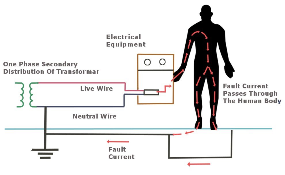
Earthing system
Ever noticed a green/yellow cable attached to a copper rod along the side of your home, probably located next to your switchboard. This cable is part of the earthing system for your electrical installation and provides a low impedance fault path for current to flow in the event of a fault. The earthing system used through-out Australia is known as the multiple earthed neutral system {MEN} and the common multiple earth system {CMEN}. This type of system will minimise voltage rise that may become live due to leakage currents on a live conductor and which allow your protective device to operate in the event of a fault.
Multiple earthed neutral {MEN} system
This type of earthing system requires a link to be made between the neutral conductors and protective earths, the link is usually made in the main switchboard between the main neutral link and earth bar, known as the MEN link. One of the main reasons why we adopt this system is due to its lower value of earth fault loop impedance and in turn will promptly trip your protective device isolating the electric circuit. A disadvantage of this system {one that does Not usually occur} if the mains neutral somehow becomes loosened or disconnected the electrical system will still operate due to the continuous path for current to flow along the earth. Depending upon were the neutral break is or how secure the earthing is, there is a possibility that the earth could give rise to the mains voltage leading to electric shock also known as Touch Voltage.
Relying on the MEN system is inadequate for protection against an electrical fault and this is why we use electrical safety switches {RCD, RCBOs} to minimize the effects of hazardous voltages.
Mistakes can often occur during testing or upgrades on main distribution boards, and we often hear stories of MEN links being left out of the installation during the reenergizing process. Therefore, it’s crucial to conduct a fault loop impedance test before switchboards are energized, ensuring the integrity of the MEN link, especially if considering a switchboard upgrade.
Earthing system components
Earth bar – most switch-boards will have an earth bar or a soldered earthing central point, protective earth from circuits, bonding protective earths, MEN link between main neutral bar and your main earth connected to ground will all be connected to the one central point.
Earth protective conductors – the conductors are used in cables for each individual circuit, bonding conductors for pipe work and main earth are all made from copper due to its low impedance.
MEN link – this connection/link can be seen between the main earth and main neutral connection point. The current carrying capacity of the MEN link must not be less than of the main neutral incoming cable and must be in the colour of green/yellow if not insulated.
Main Earth – the main earthing conductor will connect between the earth electrode and main earthing bar and its resistance should not be anymore than .5 ohms. The size of the main earth should not be less than 4mm and does not need to be any larger than 120mm.
Main Earthing Electrode – its main purpose is to take fault current to earth by connecting the neutral conductor to earth. The earth electrode is made from copper and is 12mm in diameter and 1.2 mtrs in length. It must be surrounded by moist soil once installed in the ground and corrosion must also be prevented.
The purpose of earth bonding
All conductive piping or objects within an electrical installation must be bonded and its intended use is to limit the possibility of touch voltage. You will often see the copper water pipe outside of your home bonded with an earthing strap attached and if not, it should be. Your gas pipe work will also be bonded at the metallic part of its installation. The bonding conductors should have an identification label and should be at least 4mm in size.
Testing procedures for earthing systems
Earth resistance and continuity tests – the earth system must have a low resistance to enable a fault current to operate its protective device. The low resistance will also ensure voltage on an exposed conductive part will not rise to a harmful effect. Testing of the main earth conductor, protective earth conductors and the bonding conductor should be tested using a low range resistance ohmmeter and the resistance should not exceed .5ohm. Table 8.2 in the wiring rules AS/NZS 3000:2018 should be looked upon when measuring resistance for protective conductors on each individual circuit.
Insulation resistance test – this test is to confirm that the cable is sound from insulation failure causing earth leakage currents from a live conductor. The insulation resistance test proves that the resistance of the insulation between all live conductors and earth is sound. The test must be done to prevent electric shock hazards from leakage currents, fire hazards caused by leakage currents and damage to equipment or devices. This test is completed using an insulation resistance tester and must prove that the resistance between live conductors and earth is not less than 1 MEGAOHM.
Fault loop impedance test – a test that must be done on the completion and upgrades of any electrical installation. The fault loop impedance test determines the impedance of the earthing cable verifying that its fault return path is able to withstand a fault to earth. This test is always best done when supply is connected and